Category: Data Analysis

Data analysis projects and tutorials using R, Python, and statistical methods

  • Process Capability Analysis (Cpk) in R for Semiconductor Manufacturing

    In semiconductor manufacturing, knowing that your process is in control is only half the picture. The real question is: can your process consistently produce material that meets the specification? A control chart tells you if the process is stable. A capability analysis tells you if that stable process is good enough.

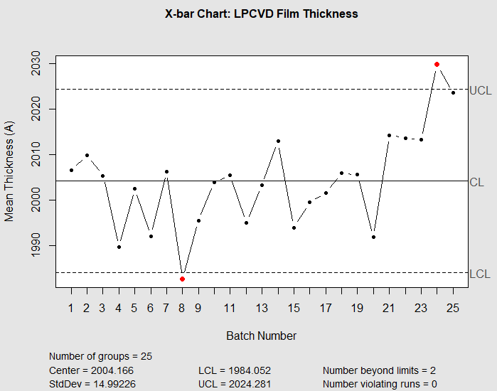
    This post builds directly on our earlier tutorial on SPC Charts in R for Semiconductor Process Monitoring. If you have not read that post yet, it covers X-bar and R charts using the qcc package, and we will be using the same simulated LPCVD silicon nitride dataset here. You can also refer back to that post for an introduction to R if needed.

    What Process Capability Actually Measures

    Process capability compares the natural variation of your process against the specification limits defined by the product design. The key insight is that control limits and specification limits are two different things:

    • Control limits are statistically derived from your process data (±3 sigma from the process mean). They tell you whether the process is stable and predictable.
    • Specification limits are engineering requirements set by product design. They define what is acceptable for the customer.

    A process can be in statistical control (all points within control limits) but still incapable of meeting the specification if the natural variation is wider than the spec tolerance. This is exactly why capability analysis matters.

    The Capability Indices: Cp and Cpk

    Two indices form the backbone of capability analysis in manufacturing:

    Cp (Process Capability Index) measures the potential capability of the process assuming it is perfectly centered between the specification limits:

    Cp = (USL - LSL) / (6 * sigma)

    Cp tells you how many times the natural process variation (6 sigma) fits inside the spec tolerance. A Cp of 1.0 means the process variation exactly matches the spec width. A Cp of 1.33 means the spec width is 33% wider than the process variation, which is generally considered the minimum acceptable for a stable process. A Cp of 1.67 or higher is typical for critical parameters.

    Cpk (Process Capability Index, adjusted for centering) accounts for how centered the process is within the spec limits:

    Cpk = min( (USL - mean) / (3 * sigma), (mean - LSL) / (3 * sigma) )

    Cpk penalizes you for being off-center. A process can have a high Cp but a low Cpk if its mean has drifted closer to one spec limit. This is common in semiconductor manufacturing where processes often run slightly above target to ensure device performance, sacrificing some margin on the upper end.

    In practice, Cpk is the more useful metric because it reflects reality. A process can be capable on paper (high Cp) but still produce out-of-spec material if the mean is not centered (low Cpk).

    Capability Analysis in R with the qcc Package

    Using the same synthetic thickness data from the SPC post, we can run capability analysis with a single function call. The qcc package provides process.capability(), which takes a qcc object of type “xbar” and specification limits as inputs.

    Let us assume the engineering specification for our LPCVD silicon nitride film is 2000 ± 60 angstroms, which gives an LSL of 1940 and a USL of 2060:

    library(qcc)
    
    # Using the same xbar chart object from the SPC post
    set.seed(42)
    n_batches <- 25
    n_wafers <- 5
    thickness <- matrix(nrow = n_batches, ncol = n_wafers)
    
    for (i in 1:n_batches) {
      drift <- ifelse(i > 20, (i - 20) * 5, 0)
      thickness[i, ] <- round(rnorm(n_wafers, mean = 2000 + drift, sd = 15), 1)
    }
    
    batch_thickness <- as.data.frame(thickness)
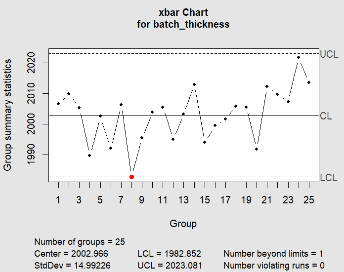
    xbar_chart <- qcc(batch_thickness, type = "xbar")
    
    # Process capability analysis
    spec_limits <- c(1940, 2060)  # LSL, USL
    cap <- process.capability(xbar_chart, spec.limits = spec_limits)
    print(cap)

    Running the above code yields the following graph

    Image

    The process.capability() function generates a histogram overlay showing the process distribution against the specification limits, with the capability indices printed. For our simulated data, the output will look something like:

    Process Capability Analysis
    
    $nobs
    [1] 125
    
    $center
    [1] 2002.966
    
    $std.dev
    [1] 14.99226
    
    $target
    [1] 2000
    
    $spec.limits
     LSL  USL 
    1940 2060 
    
    $indices
            Value     2.5%    97.5%
    Cp   1.334022 1.168084 1.499706
    Cp_l 1.399976 1.245746 1.554205
    Cp_u 1.268068 1.126833 1.409302
    Cp_k 1.268068 1.099776 1.436359
    Cpm  1.308651 1.143501 1.473546
    
    $exp
    Exp < LSL Exp > USL 
            0         0 
    
    $obs
    Obs < LSL Obs > USL 
        0.000     0.008

    We also get a histogram:

    Image

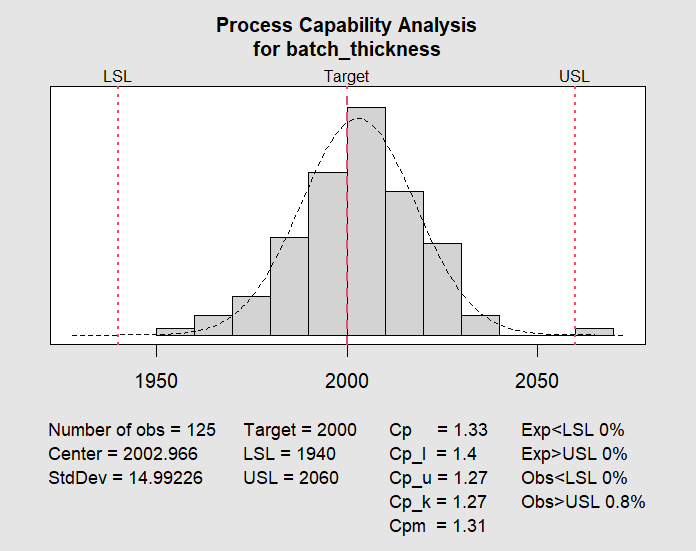
    A Cpk of 1.27 is below the commonly accepted threshold of 1.33, which makes sense because the drift in the final batches pulled the overall mean slightly upward and increased the overall variation estimate. This tells us that even though most individual measurements fall within spec, the process does not have enough margin to absorb the drift we observed.

    Interpreting the Results

    The capability output includes both short-term and long-term estimates. The qcc package reports based on the within-subgroup variation derived from the R chart, which represents the inherent short-term process capability. Key things to look for:

    • Cpk < 1.0: The process is not capable. Out-of-spec material will be produced regularly. Immediate action is needed to either reduce variation or shift the mean.
    • Cpk between 1.0 and 1.33: Marginal capability. The process can meet spec under ideal conditions, but any shift or increase in variation will produce defects. This is where most semiconductor processes operate for non-critical layers.
    • Cpk between 1.33 and 1.67: Capable process. The process has enough margin to absorb small shifts without producing defects. This is the target range for most critical parameters.
    • Cpk > 1.67: Highly capable. The process has significant margin. For ultra-critical parameters in advanced nodes, this level is often required.

    In our example, a Cpk of 1.25 is marginal. The root cause is visible in the original X-bar chart: the upward drift in batches 21 through 25 shifted the overall mean and inflated the standard deviation estimate. Without that drift, the process would easily exceed a Cpk of 1.33. This illustrates why capability analysis and control charts should always be used together. The control chart identifies when and how the process shifted; the capability analysis quantifies the impact on yield.

    Pp and Ppk: Long-Term Capability

    The qcc package also reports Pp and Ppk, which use the overall standard deviation instead of the within-subgroup estimate. The distinction matters:

    • Cp and Cpk use within-subgroup variation (short-term). They represent what the process can achieve when it is stable and in control.
    • Pp and Ppk use the total standard deviation of all data points (long-term). They represent what the process actually delivered, including any shifts, drifts, and batch-to-batch variation.

    A large gap between Cpk and Ppk indicates that the process has significant between-subgroup variation or instability. In our example, the drift causes Ppk to be noticeably lower than Cpk, confirming that the process needs corrective action before capability can improve.

    Practical Considerations for Process Engineers

    A few things to keep in mind when applying capability analysis in a real fab environment:

    • Capability requires stability. Calculating Cpk on an out-of-control process is meaningless. Always check your control charts first.
    • Sample size matters. The qcc default of at least 20 subgroups is the minimum for a reasonable estimate. Fewer subgroups produce unreliable sigma estimates.
    • Specifications are not negotiable. If Cpk is low, the solution is to reduce variation or shift the mean, not to widen the specs. That said, understanding whether the spec is a true device requirement or a legacy limit can guide prioritization.
    • Cpk should be tracked over time. A single capability study is a snapshot. Tracking Cpk on a regular basis (weekly or monthly) reveals whether process improvements are actually working.
    • Non-normal data requires care. The qcc package assumes normality for capability calculations. If your parameter is not normally distributed (particle counts, defect densities), consider transformations or distribution-specific methods.

    What Comes Next

    With control charts and capability analysis in place, you have the two foundational tools for process monitoring. The next step is often extending this framework to handle multiple correlated parameters simultaneously, which is where multivariate SPC (Hotelling’s T²) comes in. We will cover that in a future post.

    For readers interested in quantifying process improvements more rigorously, our upcoming post on Propensity Score Matching for Pre/Post CIP Analysis will show how to apply causal inference methods to evaluate the real impact of chamber maintenance events.

    Conclusion

    Process capability analysis transforms control chart data into a clear, quantitative answer to the question every process engineer faces: can this process meet the specification? Using the qcc package in R, you can go from raw thickness measurements to a Cpk value and a capability histogram in just a few lines of code. The combination of control charts for stability and capability analysis for performance gives you a complete monitoring framework that works across deposition, etch, lithography, and any semiconductor process.

  • SPC Charts in R for Semiconductor Process Monitoring

    In semiconductor manufacturing, maintaining consistent process performance across wafers and across batches is critical for device performance. One of the most powerful tools for monitoring this consistency is the Statistical Process Control (SPC) Chart. In this tutorial, we walk through how to apply SPC charts in R to simulate thin film deposition data, covering X-bar and R charts, control limit calculations, and practical interpretation for process engineers.

    If you are new to R for data analysis, you may also find my earlier post on spreadsheets as a common programming tool a useful foundation before diving into statistical methods.

    Why SPC Matters in Process Monitoring

    Semiconductor manufacturing processes require tight control over critical parameters to ensure consistent device performance, yield, and reliability. Across processes such as deposition, etch, lithography, and thermal treatments, even small variations in factors like temperature, pressure, gas flow, or power can lead to measurable shifts in material properties and device characteristics. Statistical Process Control (SPC) provides a real-time method for detecting process drift early, enabling engineers to identify and correct deviations before they result in out-of-specification wafers or reduced manufacturing yield.

    Key SPC concepts for process monitoring include:

    • X-bar chart: Tracks the average value of a critical process parameter (such as film thickness, critical dimension, or electrical performance) across subgroups, such as wafers or lots, over time to monitor process stability.
    • R chart (range chart): Tracks the variability within each subgroup, helping identify changes in process consistency, uniformity, or equipment performance.
    • Control limits: Statistically derived boundaries (typically ±3 standard deviations from the process mean) that define the expected range of normal process variation, distinct from engineering specification limits.
    • Run rules: Additional statistical tests, such as multiple consecutive points above or below the center line, used to detect subtle trends, shifts, or non-random patterns before they become significant process issues.

    Generating Synthetic Thin Film Thickness Data

    For this walkthrough, we simulate thickness measurements from a hypothetical LPCVD silicon nitride process. This is a synthetic dataset created for illustrative purposes: we model 25 subgroups (batches) with 5 wafers each, a target thickness of approximately 2000 angstroms, and an intentional drift introduced in the final batches.

    The synthetic data uses a mean of 2000 angstroms with a standard deviation of 15 angstroms, with a +5 angstrom per batch drift added in the last 5 batches. This mimics a real-world scenario where a chamber component such as a heating element begins to degrade, causing a gradual upward shift in deposited thickness.

    We deliberately avoid claiming specific crystallographic orientations or substrate materials for this simulated data. The process environment is modeled as a generic polycrystalline thin film on a crystalline substrate, using peak intensity parameters consistent with typical nitride film characterization.

    Building X-bar and R Charts in R

    The R code below uses the qcc package, one of the most widely used libraries for SPC analysis. If you do not have it installed, run install.packages("qcc") first.

    
    # Load package
    library(qcc)
    
    # Generate synthetic thickness data (angstroms)
    set.seed(42)
    n_batches <- 25
    n_wafers <- 5
    thickness <- matrix(nrow = n_batches, ncol = n_wafers)
    
    for (i in 1:n_batches) {
      drift <- ifelse(i > 20, (i - 20) * 5, 0)
      thickness[i, ] <- round(rnorm(n_wafers, mean = 2000 + drift, sd = 15), 1)
    }
    
    # Create qcc objects
    batch_thickness <- as.data.frame(thickness)
    
    # X-bar chart
    xbar_chart <- qcc(batch_thickness, type = "xbar",
                      title = "X-bar Chart: LPCVD Film Thickness",
                      xlab = "Batch Number", ylab = "Mean Thickness (A)")
    
    # R chart
    r_chart <- qcc(batch_thickness, type = "R",
                   title = "R Chart: LPCVD Film Thickness Range",
                   xlab = "Batch Number", ylab = "Range (A)")
    

    Interpreting the Control Charts

    When you run this code, the X-bar chart (shown below) will show all points within the upper and lower control limits for the first 20 batches. This indicates a stable, in-control process — exactly what a process engineer wants to see during routine production.

    Image

    Beginning around batch 21, the mean thickness will begin to climb above the center line. By batch 23, one or more points may fall above the upper control limit (UCL), signaling that the process has shifted. The R chart should remain stable throughout, indicating that the within-batch uniformity (wafer-to-wafer variation) has not changed — the problem is a shift in the mean, not an increase in variability.

    Applying Run Rules for Earlier Detection

    Standard control limits alone may not detect gradual drifts quickly enough. Run rules add sensitivity:

    • Rule 1: One point beyond the 3-sigma control limit.
    • Rule 2: Seven consecutive points on the same side of the center line.
    • Rule 3: Two out of three consecutive points beyond the 2-sigma warning limit.

    In our simulated data, the 7-point run rule (Rule 2) would flag the drift as early as batch 22, before any individual measurement exceeds the control limits. This is the practical value of SPC: catching problems before they produce out-of-spec material.

    R’s qcc package supports run rules via the rules argument. Adding rules = rulesets(c("rule1", "rule2", "rule3")) to the qcc() call will annotate violations directly on the chart.

    Practical Applications for Process Engineers

    SPC charts are not limited to thickness. They can be applied to any measurable property:

    • Refractive index from ellipsometry measurements across a wafer batch.
    • Film stress from wafer curvature measurements before and after deposition.
    • Sheet resistance for conductive thin films measured by four-point probe.
    • Uniformity calculated as (max – min) / (2 * mean) within a wafer.

    The same R code structure shown above works for any of these variables. Simply replace the thickness data with your measurement values and the control chart logic remains identical.

    Beyond Basic SPC: What Comes Next

    Once you have SPC charts running, the next step is often process capability analysis (Cpk), which compares the natural process variation to the specification limits. A Cpk value below 1.33 typically indicates that the process needs improvement. We will cover capability analysis in a future post.

    For readers interested in comparing multiple analytical approaches, our post on comparing logistic regression, SVMs, and random forests for classification demonstrates the kind of rigorous model comparison that complements SPC methodology in a broader data science toolkit.

    Conclusion

    SPC charts provide a straightforward, statistically grounded method for monitoring thin film deposition processes in real time. With just a few lines of R code using the qcc package, process engineers can detect drifts in mean thickness, identify changes in wafer-to-wafer variability, and trigger preventative maintenance before scrap material is produced. This blog uses a synthetic dataset to illustrate the workflow, but the same approach applies directly to real production data.

    The combination of X-bar charts, R charts, and run rules gives process engineers a practical early warning system. In future posts, we will extend this framework to multivariate SPC (Hotelling’s T-squared) and explore how control charts integrate with broader statistical methods such as Design of Experiments (DOE), which we will cover in a subsequent blog.

  • Predicting Diabetes: Comparing Logistic Regression, SVMs, and Random Forests

    While exploring Kaggle’s vast data science resources, I discovered an intriguing diabetes dataset and decided to develop a predictive model. The dataset structure is elegantly simple, featuring 8 independent variables and a target variable called Outcome, which identifies the presence or absence of diabetes. My objective is to create a robust model that can accurately predict diabetes based on these variables.

    Dataset Overview

    This comprehensive medical dataset contains diagnostic measurements specifically collected for diabetes prediction based on various health indicators. It encompasses 768 female patient records, with each record containing 8 distinct health parameters. The Outcome variable serves as the binary classifier, indicating diabetes presence (1) or absence (0). This dataset serves as an excellent resource for training and evaluating machine learning classification models in the context of diabetes prediction.

    • Pregnancies (Integer): Total pregnancy count for each patient.
    • Glucose (Integer): Post 2-hour oral glucose tolerance test plasma concentration (mg/dL).
    • BloodPressure (Integer): Measured diastolic blood pressure (mm Hg).
    • SkinThickness (Integer): Measured triceps skin fold thickness (mm).
    • Insulin (Integer): Measured 2-hour serum insulin levels (mu U/ml).
    • BMI (Float): Calculated body mass index using weight(kg)/height(m)^2.
    • DiabetesPedigreeFunction (Float): Calculated genetic diabetes predisposition score based on family history.
    • Age (Integer): Patient’s age in years.
    • Outcome (Binary): Target variable indicating diabetes (1) or no diabetes (0).

    This valuable dataset, adapted from the National Institute of Diabetes and Digestive and Kidney Diseases (NIDDK), is frequently utilized in data science research focusing on healthcare analytics and medical diagnostics.

    Exploratory Data Analysis

    Initial data examination reveals a significant concern: multiple variables including Blood Pressure, Glucose, Skin Thickness, Insulin, and BMI contain zero values. These likely represent measurement errors, necessitating their removal for accurate analysis.

    diabetes <- read.csv('diabetes_dataset.csv') #Read Data
    summary(diabetes)
    Diabetes Summary

    Post removal of zero values, our dataset reduces to 392 observations. Though smaller, this sample size remains adequate for developing a reliable predictive model.

    diabetes <- diabetes %>%
      filter(BloodPressure != 0) %>%
      filter(Glucose != 0) %>%
      filter(SkinThickness != 0) %>%
      filter(Insulin != 0) %>%
      filter(BMI != 0)
    hist(diabetes$Age)
    hist(diabetes$DiabetesPedigreeFunction)
    hist(diabetes$BMI)
    hist(diabetes$Insulin)
    hist(diabetes$SkinThickness)
    hist(diabetes$BloodPressure)
    hist(diabetes$Glucose)
    hist(diabetes$Pregnancies)
    Histograms

    Subsequently, we analyze the distribution patterns of all independent variables.

    The analysis reveals that most variables, except pregnancy, age, and insulin, deviate from normal distribution. The non-normal distribution of pregnancy data aligns with logical expectations.

    Data Preprocessing

    We implement these specific transformations:

    • Insulin: Box-Cox Transform
    • Age: Box-Cox Transform
    • Age: Square Root Transform
    #PreProcess Data to Get everything into Normal Distribution
    
    #Applying Box-Cox Transform on Age
    
    boxcox(diabetes$Age ~ 1)
    diabetes$boxcoxAge <- (diabetes$Age^-1.4 - 1)/-1.4
    hist(diabetes$boxcoxAge)
    
    #Applying Box-Cox Transform on Insulin
    
    boxcox(diabetes$Insulin ~ 1)
    diabetes$boxcoxInsulin <- (diabetes$Insulin^0.05 -1)/0.05
    hist(diabetes$boxcoxInsulin)
    
    #Applying Box-Cox Transform on Pregnancies
    diabetes$Pregnancies
    diabetes$sqrtPregnancies <- sqrt(diabetes$Pregnancies)
    hist(diabetes$sqrtPregnancies)

    Finally, we apply max-min scaling to normalize all values between 0 and 1, effectively preventing any data artifacts from influencing our analysis.

    #Storing relevant variables in a new dataframe and scaling the data
    
    diabetes.clean <- diabetes %>%
      dplyr::select(
        Outcome,
        DiabetesPedigreeFunction,
        sqrtPregnancies,
        SkinThickness,
        boxcoxInsulin,
        boxcoxAge,
        BMI,
        Glucose,
        BloodPressure
      )
      
    
    preproc <- preProcess(diabetes.clean, method = "range")
    scaled.diabetes.clean <- predict(preproc, diabetes.clean)
    
    head(scaled.diabetes.clean)
    str(scaled.diabetes.clean)
    scaled.diabetes.clean$Outcome <- as.factor(scaled.diabetes.clean$Outcome)
    

    Looking for correlations in the variables

    Upon analyzing the correlation matrix, the data science analysis reveals minimal significant correlations among the variables, suggesting we can proceed with treating them as independent predictors in our modeling approach.

    # Looking for Correlations within the Data
    
    num.cols <- sapply(scaled.diabetes.clean, is.numeric)
    cor.data <- cor(scaled.diabetes.clean[,num.cols])
    cor.data
    corrplot(cor.data, method = 'color')
    Corrplot

    Splitting the data into training and testing set

    For model development and evaluation, we implement a standard data partitioning strategy, allocating 70% of the observations to the training dataset and reserving the remaining 30% for testing purposes.

    #Splitting Data into train and test sets
    
    sample <- sample.split(scaled.diabetes.clean$Outcome, SplitRatio = 0.7)
    train = subset(scaled.diabetes.clean, sample == TRUE)
    test = subset(scaled.diabetes.clean, sample == FALSE)

    Building a Model

    Our predictive modeling approach incorporates three distinct machine learning techniques: Logistic Regression, Support Vector Machines, and Random Forests.

    Logistic Regression

    The logistic regression implementation yields a respectable accuracy of 77.12%. The model identifies Age, BMI, and Glucose as significant predictors of diabetes, with the diabetes pedigree function showing moderate influence. This suggests that while genetic predisposition plays a role, lifestyle factors remain crucial in diabetes prevention.

    Support Vector Machines

    Despite parameter tuning efforts, the Support Vector Machines algorithm demonstrates slightly lower performance, achieving 74.9% accuracy compared to the logistic regression model.

    Random Forest

    Random Forests emerge as the superior performer among the three approaches, delivering the highest accuracy at 79.56%.

    A critical observation across all models is the notably lower proportion of Type I errors. In this medical context, false negatives pose a greater risk than false positives, making this characteristic particularly relevant.

    Comparing the Models

    A comparative analysis of model performance metrics reveals Random Forests as the top performer, though there remains room for improvement. It’s worth noting that the necessity to exclude numerous observations due to measurement inconsistencies may have impacted model performance. While this model shows promise as a preliminary diabetes screening tool with reasonable accuracy, developing a more precise predictive model would require additional data points and refined measurements.

    Code

    ### LOGISTIC REGRESSION ###
    
    log.model <- glm(formula=Outcome ~ . , family = binomial(link='logit'),data = train)
    summary(log.model)
    fitted.probabilities <- predict(log.model,newdata=test,type='response')
    fitted.results <- ifelse(fitted.probabilities > 0.5,1,0)
    misClasificError <- mean(fitted.results != test$Outcome)
    print(paste('Accuracy',1-misClasificError))
    table(test$Outcome, fitted.probabilities > 0.5)
    
    ### SVM ####
    
    svm.model <- svm(Outcome ~., data = train)
    summary(svm.model)
    predicted.svm.Outcome <- predict(svm.model, test)
    table(predicted.svm.Outcome, test[,1])
    tune.results <- tune(svm, 
                         train.x = train[2:9], 
                         train.y = train[,1], 
                         kernel = 'radial',
                         ranges = list(cost=c(1.25, 1.5, 1.75), gamma = c(0.25, 0.3, 0.35)))
    summary(tune.results)
    tuned.svm.model <- svm(Outcome ~., 
                           data = train, 
                           kernel = "radial",
                           cost = 1.25,
                           gamma = 0.25,
                           probability = TRUE)
    summary(tuned.svm.model)
    print(svm.model)
    tuned.predicted.svm.Outcome <- predict(tuned.svm.model, test)
    table(tuned.predicted.svm.Outcome, test[,1])
    Table